Compact Crossed-Dipole (Turnstile) Antenna for Global Navigation Satellite System (GNSS) Applications
Problem Description
Design Challenges
The design and implementation of the crossed-dipole antenna for GNSS applications [1] is very challenging due to the following reasons:
Very high performance requirements in terms of return loss and axial ratio.
Highly compact design for military gear.
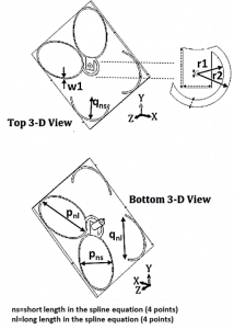
Unconventional non-rectangular (egg-shaped) driven and passive elements.
High Performance Requirements
The performance requirements are set to according to the objectives of the 2014/2015 Innovate UK – the Small Business Research Initiative (SBRI) Global Navigation Satellite System (GNSS) Antenna Design Competition.
An antenna design competition co-funded by the Ministry of Defence (MoD), UK and Innovate UK.
Layout of the crossed-dipole GNSS antenna.
The high-performance requirements are stated as follows:
Bandwidth
1.1 GHz to 1.7 GHz
Maximum Return Loss over the Bandwidth
Smaller than or equal to -14 dB
Maximum Axial Ratio (AR) over the Bandwidth
Smaller than or equal to 3 dB
Size (highly compact design for placement on military gear)
64.0 mm × 64.0 mm × 10.6 mm
Winning Antenna Design
Successful antenna design proposed and implemented by BAE Systems Applied Intelligence Ltd., UK and University of Liverpool, UK:
Bandwidth
1.1 GHz to 1.7 GHz
Maximum Return Loss over the Bandwidth
-9.44 dB
Maximum Axial Ratio (AR) over the Bandwidth
5.07 dB
Size (highly compact design for placement on military gear)
64.0 mm × 64.0 mm × 10.6 mm
AI-driven Design with SADEA-III
The optimization problem is stated as follows:
Maximum reflection coefficient (S11) < -14 dB (1.1 GHz to 1.7 GHz)
Maximum axial ratio (AR) < 3 dB (1.1 GHz to 1.7 GHz)
Search Ranges of the Design Parameters
Layout of the antenna
Synthesis and Measurement Results
The design obtained by SADEA-III [2] is verified through a physical implementation.
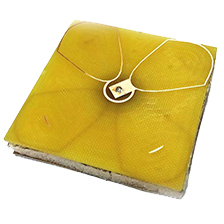
The fabricated antenna.
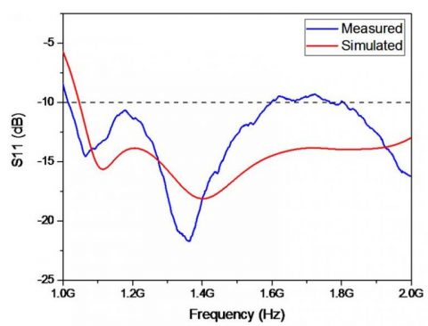
Free-space return loss.
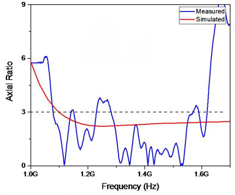
Free-space axial ratio.
For this case:
The synthesized antenna by SADEA-III obtains a maximum return loss of -15.2 dB and a maximum axial ratio of 2.9 dB over the bandwidth in one day.
The synthesized antenna by SADEA-III outperforms the winning antenna design in terms of return loss and axial ratio.
The measurement results are in close agreement with the simulation results.
The size of the fabricated antenna is 64.0 mm × 64.0mm × 10.6 mm, which is compact.
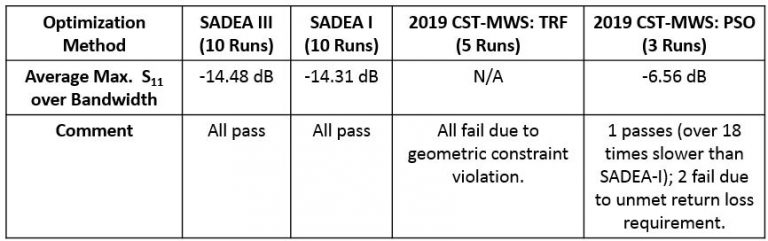
Comparison with Other Methods
The performances of SADEA-III [2] and SADEA-I [3] are compared with the following methods:
A sigma value of unity is used to direct the search towards global optimum and all initial designs for each run are randomly generated using Latin hypercube sampling.
Results of all methods.
Note that results from designs with geometric constraint violation are not included and are designated as not applicable (N/A) because in practice, such designs cannot be used due to geometric incongruities.
Convergence trends for SADEA-III (3 parallel EM simulations), SADEA-I and 2019 CST-MWS: PSO.